
Cisco Packet Tracer
-
This project was aimed at simulating a small office network consisting of four VLANs in Cisco Packet Tracer to gain a better understanding of networking concepts, specifically the following:
DHCP Configuration
Inter-VLAN Routing
Network Address Translation (NAT)
Switch Configuration
-
Cisco Packet Tracer
End Devices: 5 PCs (PC0, PC1, PC2, PC3, PC4), 2 IP Phones (IP Phone 0, IP Phone 1), 1 Server (Google Server), 1 Wireless Laptop
Network Devices: 3 Switches (Core Switch, Access Switch 1, Access Switch 2), 2 Routers (ISP Router, Internet Backbone)
Cables: Copper Straight-Through Cables, Single Mode Fiber Cable
-
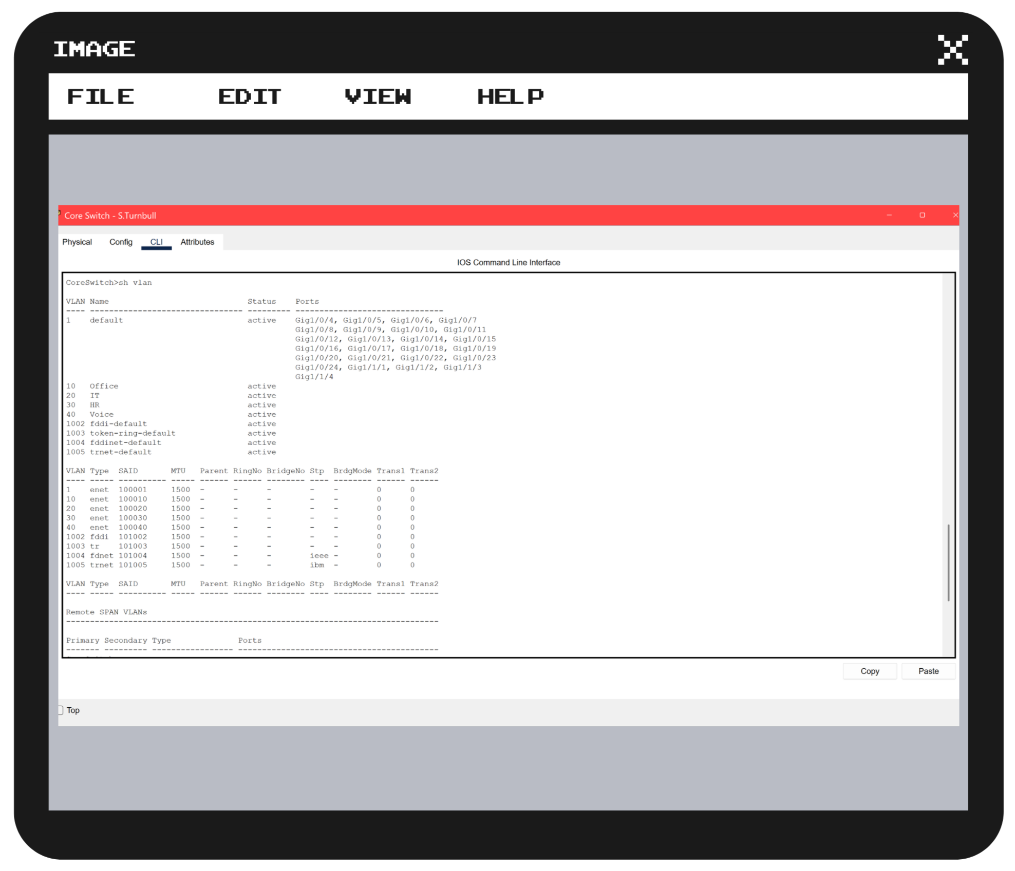
Switch Configuration: VLANs were successfully created on each switch to divide a physical network into multiple virtual or logical networks
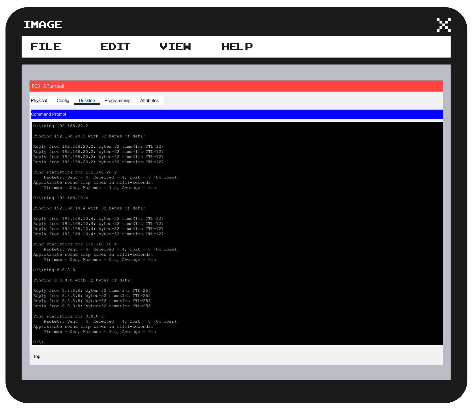
Successful Inter-VLAN Routing: PCs in different VLANs and sub-interfaces were able to ping and receive replies from each other
DHCP Assignment: After configuring DHCP pools on the ISP Router to enable automatic assignment of IP addresses, all the devices succeeded in fully making use of this deployment
NAT Employment: The implementation of NAT demonstrated the devices’ ability to use a single public IP to access the Internet and control traffic, as represented by the Internet Backbone and Google Server
-
The introduction of VLANs and Inter-VLAN Routing adds the convenience of less hardware, space, and cost, as it provides a logical avenue for a single hardware device to be split into several networks while being able to contact devices across divisions
Just a single misconfiguration can cause a breakdown in communication such as IP address (DHCP) conflicts from not excluding static addresses
Core Switch Configuration
After connecting all the devices, click the core switch, go to CLI, and enter the en and conf t commands to change the device hostname from Multilayer Switch 0 to Core Switch using the hostname command: hostname CoreSwitch
Create VLANs for regular office staff, HR, IT, and Voice by running the vlan and name commands for each VLAN, respectively. For example, vlan 10 followed by name Office
Configure trunk ports for each access switch; for example, int gi1/0/1, switchport mode trunk, switchport trunk allowed vlan all, then type wr
internet backbone and google Server configuration
Click on Internet Backbone, go to CLI, enter global configuration mode, type int loopback 0, then ip address 8.8.8.8 255.255.255.255 to simulate the public internet
Go to the ISP Router; in the terminal, run ip route 0.0.0.0 0.0.0.0 8.8.8.8 to handle the internet traffic default pathway
Google Server and assign a public static IP address by going to Desktop, then IP Configuration, check that the ip address is 8.8.8.8
Go to Services, select HTTPS DNS, turn it on, type in the specific web address such as, ://google.com, enter the server’s IP address, and select Add
access Switch 1 Configuration
On Switch0, enter global configuration mode, change the hostname to Access Switch 1, and create VLANs 10, 20, and 40
Configure the switch port (uplink) connected to the core switch to trunk mode by running the following commands consecutively: int gi0/1, switchport mode trunk, switchport trunk allowed vlan 10, 20, 40
For the computers on VLAN 10, assign access and voice ports via int range fa0/1-5, switchport mode access, switchport access vlan 10, switchport voice vlan 40
For the HR computers on VLAN 20, assign access and voice ports by using int range fa0/6-10, switchport mode access, switchport access vlan 20, switchport voice vlan 40, and wr
access Switch 2 Configuration
Click Switch1, change the name to Access Switch 2, and create VLAN 30 for IT
Configure the uplink as a trunk, assign access and voice ports to VLAN 30, and save the configuration
ISP Router Configuration for dhcp and inter-vlan routing
On Access Switch 2, configure a trunk port for the ISP Router using the port connected to the router from the core switch: int g1/0/3, switchport mode trunk, switchport trunk allowed vlan all
On Router-0, change the hostname to ISP Router and create sub-interfaces for each VLAN, e.g.: int gi0/0.10, encapsulation dot1Q 10, ip address 192.168.10.1 255.255.255.0, exit
Enable the router’s interface connected to the core switch by typing int gi0/0, no shut, and save the configuration
Exclude static sub-interface IP addresses: e.g., ip dhcp excluded-address 192.168.10.1
Configure DHCP pools: ip dhcp pool Office_Pool, network 192.168.10.0 255.255.255.0, default-router 192.168.10.1, exit
Access point and Laptop configuration
Click on Access Point0, go to the Config tab, navigate to Port 1, set a network name (VLAN10-WiFi), and enter a WPA2-PSK passphrase
Go to Access Switch 2, and in CLI connect the switch port connected to the access point by creating VLAN 10 and entering: en, conf t, int fa0/3, switchport mode access, switchport access vlan 10, no shut, exit, and wr
Click on the laptop and select the Config tab, turn off the laptop, and replace the existing wired module with the wireless (WPC300N) module
Turn the laptop on, select the Desktop tab, open PC Wireless, and connect it
NAT and ACCESS LIst configuration
Configure Network Address Translation (NAT) on the ISP Router by defining the outside and inside interfaces: e.g. it gi0/1, ip nat outside, exit & int gi0/0.10, ip nat inside, exit
Create an access list for the internal subnets: e.g., access-list 1 permit 192.168.10.0 0.0.0.255
Enable NAT Overload or PAT: ip nat inside source list 1 int gi0/1 overload, exit, wr
Check the DHCP assignment on each PC, ping among PCs to check connectivity, and ping the server to test external connections